Description:
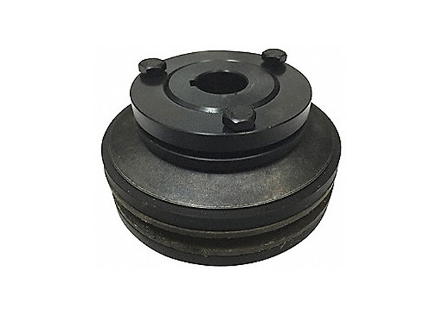
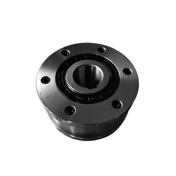
Integrated Freewheels FXM are sprag free -wheels without bearing support and with sprag lift-off X.The sprag lift-off X ensures freewheel one way clutch operation when the inner ring rotates at high speed.
The freewheels FXM are used as:
1. Backstops
2. Overrunning Clutches
for applications with high speed freewheeling operation and when used as an overrunning clutch with low speed driving operation.
Nominal torques up to 888 000 N.m.
Bores up to 460 mm. Many standard bores are available.
Dimensions and Capacities:

Freewheel Size | Nominal torque(Nm) | Nominal torque at existing run out T.I.R.(Nm) | Sprag lift-off at inner ring speed min-1 | Max. speed |
| ↗ | 0 | A | ↗ | 0,1 | A | ↗ | 0,2 | A | ↗ | 0,3 | A | ↗ | 0,4 | A | ↗ | 0,5 | A |
| Inner ring overruns min-1 | Outer ring drives min-1 |
FXM | 31- 17 | 110 | 110 | 105 | 100 |
|
| 890 | 5 000 | 356 |
FXM | 38-17 | 180 | 170 | 160 | 150 |
|
| 860 | 5 000 | 344 |
FXM | 46-25 | 460 | 450 | 440 | 430 |
|
| 820 | 5 000 | 328 |
FXM | 51 - 25 | 560 | 550 | 540 | 530 |
|
| 750 | 5 000 | 300 |
FXM | 56 - 25 | 660 | 650 | 640 | 630 |
|
| 730 | 5 000 | 292 |
FXM | 61 - 19 | 520 | 500 | 480 | 460 |
|
| 750 | 5 000 | 300 |
FXM | 66 - 25 | 950 | 930 | 910 | 890 |
|
| 700 | 5 000 | 280 |
FXM | 76 - 25 | 1 200 | 1 170 | 1 140 | 1 110 |
|
| 670 | 5 000 | 268 |
FXM | 86 - 25 | 1 600 | 1 550 | 1 500 | 1 450 |
|
| 630 | 5 000 | 252 |
FXM | 101 -25 | 2 100 | 2 050 | 2 000 | 1 950 |
|
| 610 | 5 000 | 244 |
FXM | 85 -40 | 2 500 | 2 400 | 2 300 | 2 300 | 2 200 | 1 850 | 430 | 6 000 | 172 |
FXM | 100 -40 | 3 700 | 3 600 | 3 400 | 3 400 | 2 900 | 2 400 | 400 | 4 500 | 160 |
FXM | 120 -50 | 7 700 | 7 600 | 7 500 | 6 100 | 5 100 | 4 200 | 320 | 4 000 | 128 |
FXM | 140 -50 | 10 100 | 10 000 | 9 800 | 8 400 | 7 000 | 5 800 | 320 | 3 000 | 128 |
FXM | 170 -63 | 20 500 | 20 500 | 19 500 | 15 500 | 13 000 | 12 000 | 250 | 2 700 | 100 |
FXM | 200 -63 | 31 000 | 27 500 | 22 000 | 18 000 | 15 500 | 14 000 | 240 | 2 100 | 96 |
FXM data sheet:
Type | Bore d | A | B | D | E | F | G | J | L | P | T | U | V | W | Z** | Weight |
| mm | mm | mm | mm | mm | mm | mm | mm | mm | mm | mm | mm |
| mm | mm | mm | mm | mm | mm | mm |
| kg |
FXM 31 -17 | 20* |
|
|
|
|
| 20* | 17 | 25 | 85 | 41 | 55 | M6 | 31 | 24 | 1,0 | 70 | 15 | 6 | 21 | 6 | 0,8 |
FXM 38 -17 | 25* |
|
|
|
|
| 25* | 17 | 25 | 90 | 48 | 62 | M6 | 38 | 24 | 1,0 | 75 | 15 | 6 | 21 | 6 | 0,9 |
FXM 46 -25 | 25 |
|
|
|
|
| 30 | 25 | 35 | 95 | 56 | 70 | M6 | 46 | 35 | 1,0 | 82 | 15 | 6 | 21 | 6 | 1,3 |
FXM 51 -25 | 25 | 30 | 35 |
|
|
| 36 | 25 | 35 | 105 | 62 | 75 | M6 | 51 | 35 | 1,0 | 90 | 15 | 6 | 21 | 6 | 1,7 |
FXM 56 -25 | 35 |
|
|
|
|
| 40 | 25 | 35 | 110 | 66 | 80 | M6 | 56 | 35 | 1,0 | 96 | 15 | 6 | 21 | 8 | 1,8 |
FXM 61 -19 | 30 | 35 | 40 |
|
|
| 45* | 19 | 27 | 120 | 74 | 85 | M8 | 61 | 25 | 1,0 | 105 | 15 | 6 | 21 | 6 | 1,8 |
FXM 66 -25 | 35 | 40 | 45 |
|
|
| 48* | 25 | 35 | 132 | 82 | 90 | M8 | 66 | 35 | 1,0 | 115 | 15 | 8 | 23 | 8 | 2,8 |
FXM 76 -25 | 45 | 55 |
|
|
|
| 60* | 25 | 35 | 140 | 92 | 100 | M8 | 76 | 35 | 1,0 | 125 | 15 | 8 | 23 | 8 | 3,1 |
FXM 86 -25 | 40 | 45 | 50 | 60 | 65 |
| 70* | 25 | 40 | 150 | 102 | 110 | M8 | 86 | 40 | 1,0 | 132 | 15 | 8 | 23 | 8 | 4,2 |
FXM 101 -25 | 55 | 70 |
|
|
|
| 80* | 25 | 50 | 175 | 117 | 125 | M10 | 101 | 50 | 1,0 | 155 | 20 | 8 | 28 | 8 | 6,9 |
FXM 85 -40 | 45 | 50 | 60 | 65 |
|
| 65 | 40 | 50 | 175 | 102 | 125 | M10 | 85 | 60 | 1,0 | 155 | 20 | 8 | 28 | 8 | 7,4 |
FXM 100 -40 | 45 | 50 | 55 | 60 | 70 | 75 | 80* | 40 | 50 | 190 | 130 | 140 | M10 | 100 | 60 | 1,5 | 165 | 25 | 10 | 35 | 12 | 8,8 |
FXM 120 -50 | 60 | 65 | 70 | 75 | 80 | 95 | 95 | 50 | 60 | 210 | 150 | 160 | M10 | 120 | 70 | 1,5 | 185 | 25 | 10 | 35 | 12 | 12,7 |
FXM 140 -50 | 65 | 90 | 100 | 110 |
|
| 110 | 50 | 70 | 245 | 170 | 180 | M12 | 140 | 70 | 2,0 | 218 | 25 | 12 | 35 | 12 | 19,8 |
FXM 170 -63 | 70 | 85 | 90 | 100 | 120 |
| 130 | 63 | 80 | 290 | 200 | 210 | M16 | 170 | 80 | 2,0 | 258 | 28 | 12 | 38 | 12 | 33,0 |
FXM 200 -63 | 130 |
|
|
|
|
| 155 | 63 | 80 | 310 | 230 | 240 | M16 | 200 | 80 | 2,0 | 278 | 32 | 12 | 42 | 12 | 32,0 |
FXM 240 - 63 |
|
|
|
|
|
| 185 | 63 | 80 | 400 | 280 | 310 | M20 | 240 | 90 | 2,0 | 360 | 48 | 15 | 60 | 12 | 60,0 |
FXM 240 - 96 |
|
|
|
|
|
| 185 | 96 | 125 | 420 | 280 | 310 | M24 | 240 | 120 | 2,0 | 370 | 48 | 18 | 60 | 16 | 95,0 |
FXM 260 - 63 |
|
|
|
|
|
| 205 | 63 | 80 | 430 | 300 | 330 | M20 | 260 | 105 | 2,0 | 380 | 48 | 18 | 60 | 16 | 75,0 |
FXM 290 - 70 |
|
|
|
|
|
| 230 | 70 | 80 | 460 | 330 | 360 | M20 | 290 | 105 | 2,0 | 410 | 48 | 18 | 60 | 16 | 90,0 |
FXM 290 - 96 |
|
|
|
|
|
| 230 | 96 | 110 | 460 | 330 | 360 | M20 | 290 | 120 | 2,0 | 410 | 48 | 18 | 60 | 16 | 91,0 |
FXM 310 - 70 |
|
|
|
|
|
| 240 | 70 | 125 | 497 | 360 | 380 | M20 | 310 | 110 | 3,0 | 450 | 48 | 18 | 60 | 24 | 135,0 |
FXM 310 - 96 |
|
|
|
|
|
| 240 | 96 | 125 | 497 | 360 | 380 | M20 | 310 | 120 | 3,0 | 450 | 48 | 18 | 60 | 24 | 145,0 |
FXM 320 - 70 |
|
|
|
|
|
| 250 | 70 | 80 | 490 | 360 | 390 | M24 | 320 | 105 | 3,0 | 440 | 55 | 20 | 68 | 16 | 105,0 |
FXM 360 - 100 |
|
|
|
|
|
| 280 | 100 | 120 | 540 | 400 | 430 | M24 | 360 | 125 | 3,0 | 500 | 55 | 20 | 68 | 24 | 170,0 |
FXM 410 - 100 |
|
|
|
|
|
| 320 | 100 | 120 | 630 | 460 | 480 | M24 | 410 | 125 | 3,0 | 560 | 55 | 20 | 68 | 24 | 245,0 |
FXM 2410 - 100 |
|
|
|
|
|
| 320 | 200 | 220 | 630 | 460 | 480 | M30 | 410 | 220 | 3,0 | 560 | 55 | 20 | 68 | 24 | 440,0 |
Notes:
The maximum transmissible torque is 2 times the specified nominal torque.
The theoretical nominal torque applies only for ideal concentricity between the inner and outer ring. In practice, the concentricity is affected by the bearing play and centering errors of the neigh bouring parts.
Then the nominal torques specified in the table apply, whilst taking into consideration the existing run out (T.I.R.).Higher speeds upon request.
Mounting:
Integrated Freewheels FXM are without bearing support. Concentric alignment of inner and
outer ring must be provided by the customer. The permissible run out (T.I.R.) must be ob -
served.The Integrated Freewheel FXM is centered via the outer track F on the customer attachment part and bolted to this (refer to figure 67-1). The tolerance of the pilot diameter of the attachment part must be ISO h6 or h7.
The tolerance of the shaft must be ISO h6 or j6. For fitting to shaft ends, end covers can be supplied upon request (refer to figure 67-3).
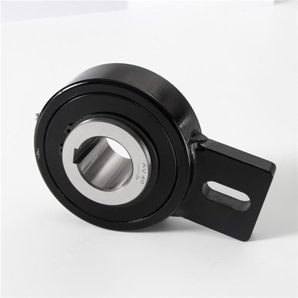
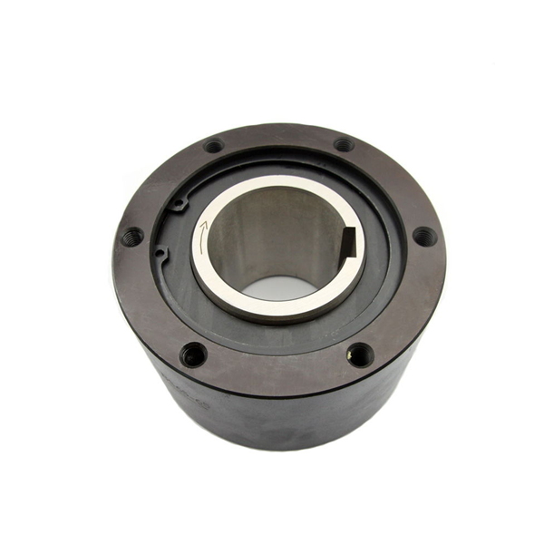
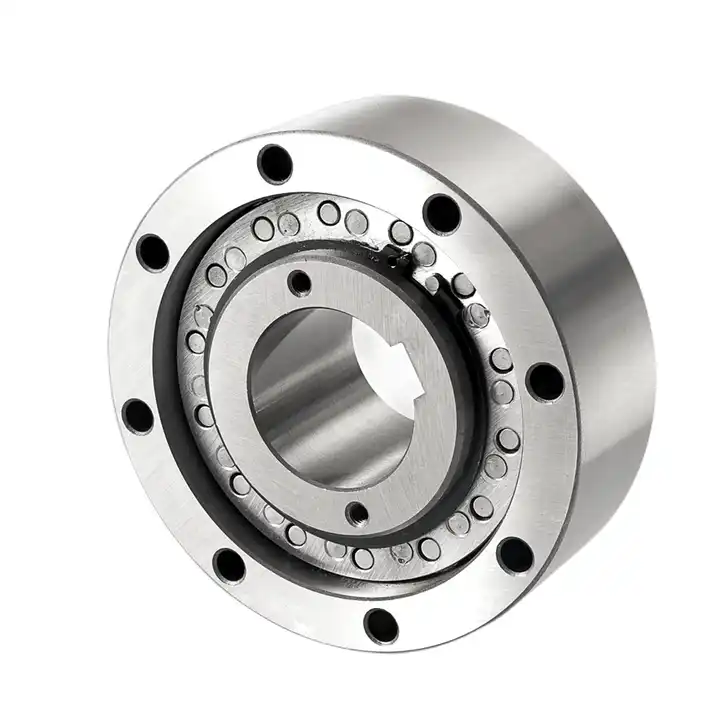
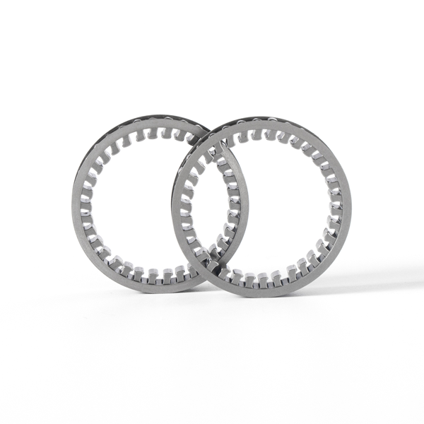
Producty display: