Description:
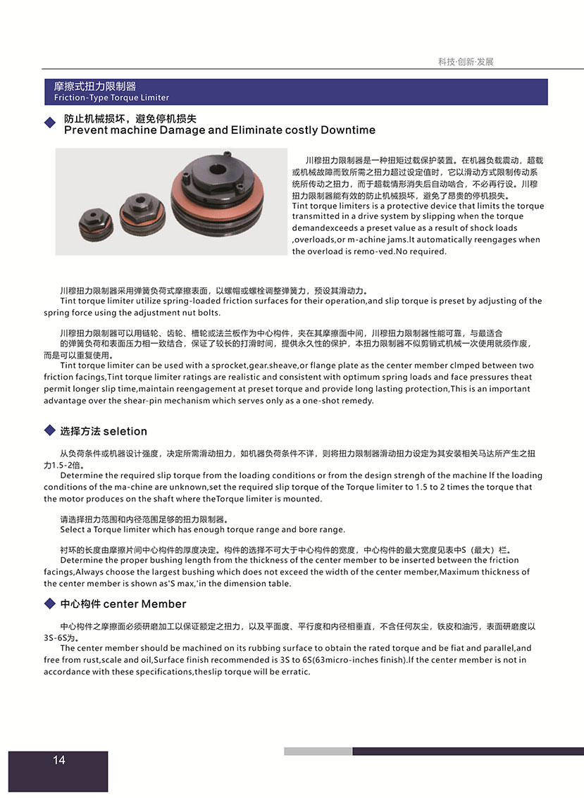
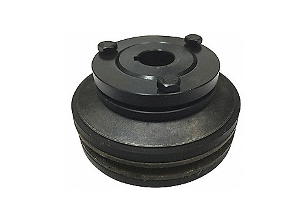
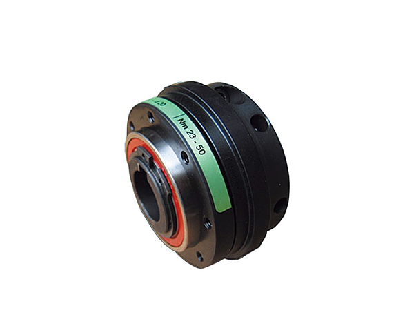
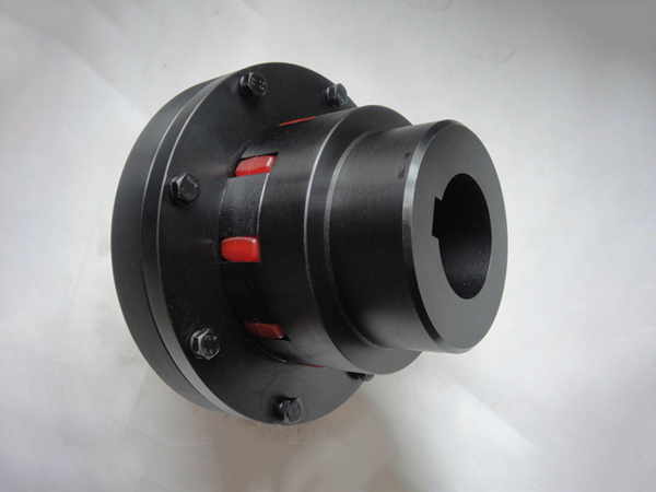
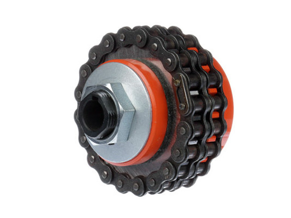
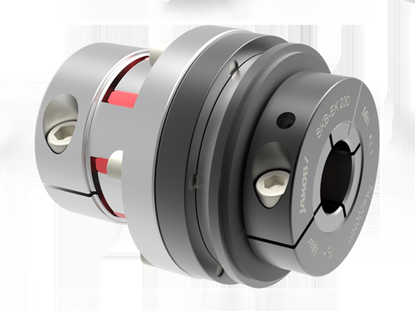
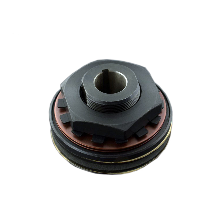
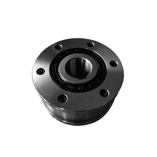
Friction torque limiter is a protective device that limits the torque transmitted in a drive system by slipping when the torqueDemand exceeds a preset value as a result of shock loads overloads or machine jams.It automatically reengages when the overload is removed. No required.
Tint torque limiter utilize spring-loaded friction surfaces for their operation,and slip torque is preset by adjusting of thespring force using the adjustment nut bolts.
Tint torque limiter can be used with a sprocket,gear.sheave,or flange plate as the center member clmped between twofriction facings,Tint torque limiter ratings are realistic and consistent with optimum spring loads and face pressures theatpermit longer slip time,maintain reengagement at preset torque and provide long lasting protection,This is an importantadvantage over the shear-pin mechanism which serves only as a one-shot remedy.
Seletion:
Determine the required slip torque from the loading conditions or from the design strengh of the machine If the loadingconditions of the machine are unknown, set the required slip torque of the Torque limiter to 1.5 to 2times the torque thatthe motor produces on the shaft where theTorque limiter is mounted.
Select a Torque limiter which has enough torque range and bore range.
Determine the proper bushing length from the thickness of the center member to be inserted between the frictionfacings,Always choose the largest bushing which does not exceed the width of the center member,Maximum thickness ofthe center member is shown as"S max,' in the dimension table.
Center Member:
The center member should be machined on its rubbing surface to obtain the rated torque and be fiat and parallel,andfree from rust,scale and oil, Surface finish recommended is 3S to 6$(63micro-inches finish).lf the center member is not inaccordance with these specifications,theslip torque will be erratic.
Setting Torque:
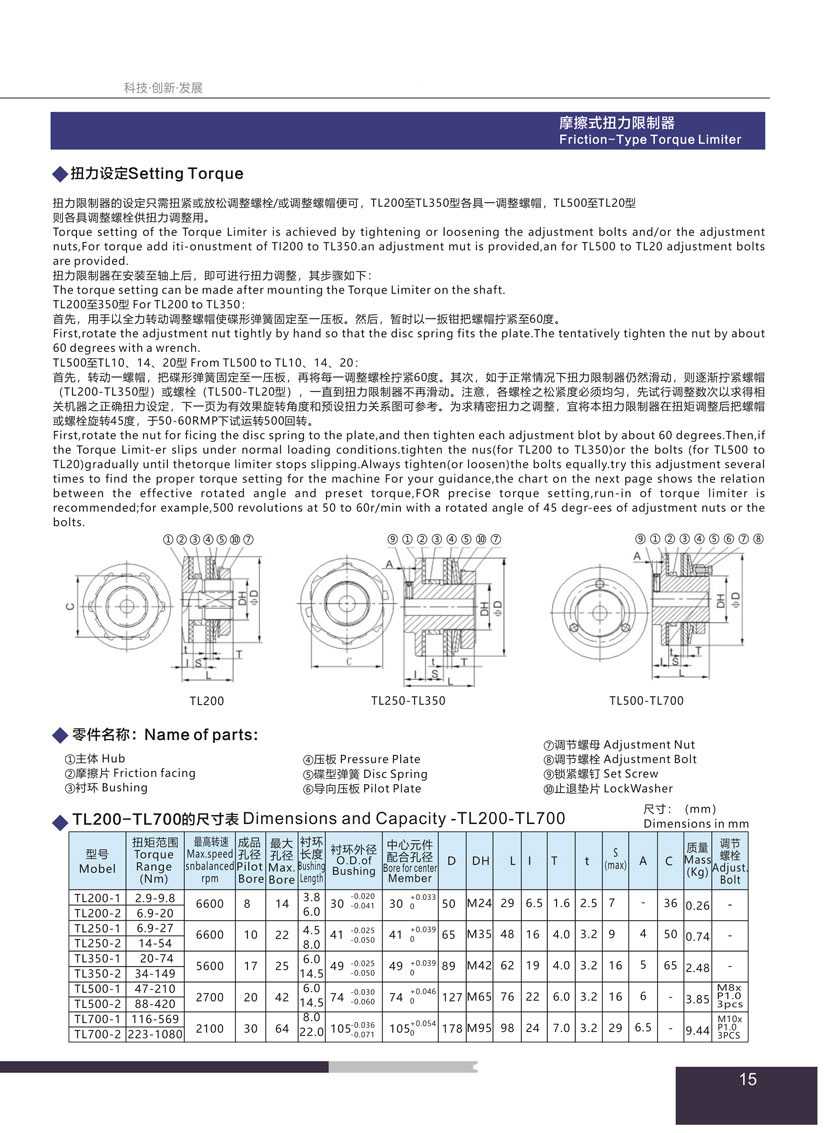
Torque setting of the Torque Limiter is achieved by tightening or loosening the adjustment bolts and/or the adjustmentnuts,For torque add iti-onustment of T1200 to TL350.an adjustment mut is provided,an for TL500 to TL20 adjustment boltsare provided.
First,rotate the adjustment nut tightly by hand so that the disc spring fits the plate.The tentatively tighten the nut by about60 degrees with a wrench.
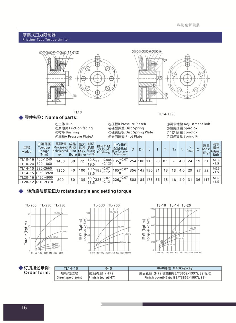
First,rotate the nut for ficing the disc spring to the plate,and then tighten each adjustment blot by about 60 degrees.Then,ifthe Torque Limit-er slips under normal loading conditions.tighten the nus(for TL200 to TL350)or the bolts (for TL500 toTL20)gradually until thetorque limiter stops slipping.Always tighten(or loosen)the bolts equally,try this adjustment severaltimes to find the proper torque setting for the machine For your guidance,the chart on the next page shows the relationbetween the effective rotated angle and preset torque,FOR precise torque setting,run-in of torque limiter isrecommended;for example,500 revolutions at 50 to 60r/min with a rotated angle of 45 degr-ees of adjustment nuts or thebolts.
