


Why Do Inclined Conveyors Roll Back When the Motor Stops?
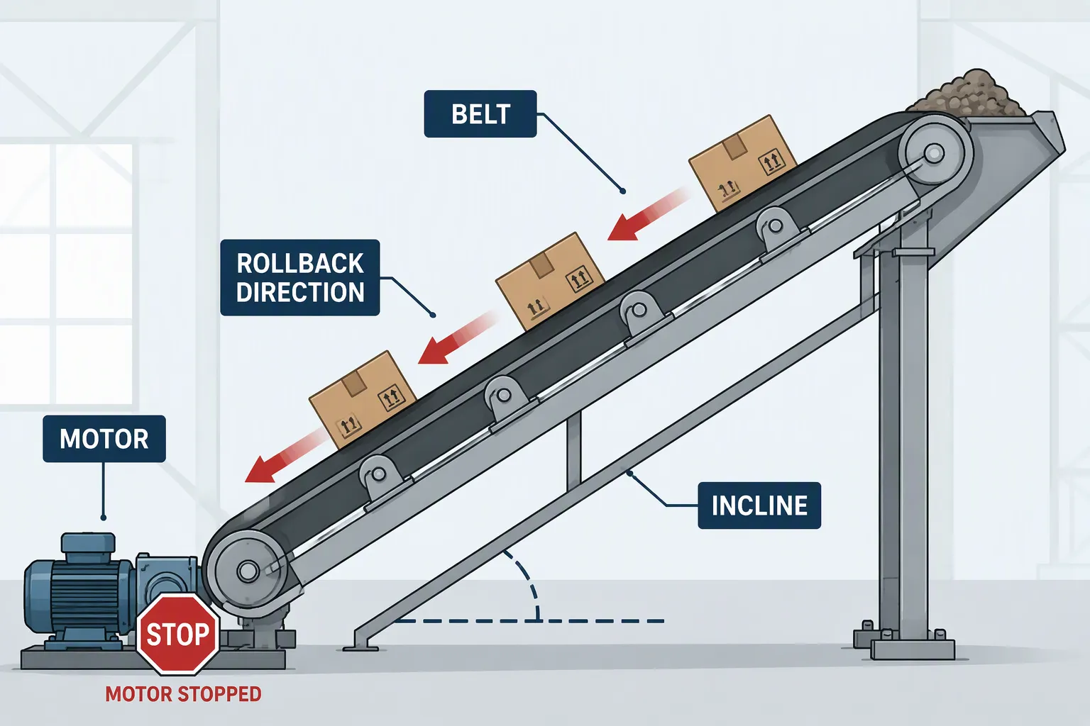
Inclined conveyors roll back because gravity pulls the loaded belt downhill the instant the motor stops supplying forward force. Without a mechanical holdback device, the belt becomes a runaway mass. This article explains the physics of rollback, separates the two different failures that are routinely confused with each other, and shows how a backstop prevents reverse rotation, how to size one, and how to keep it working.
Key Takeaways
Gravity pulls the loaded belt downhill the moment the motor stops supplying torque.
Two different failures are often confused: material slipping on the belt surface, and the entire belt running backward (runback). Only the second is solved by a backstop.
Cleated and chevron belts hold material in place, but they do not stop the belt itself from reversing.
Rollback causes serious injuries, equipment damage, spillage, and costly downtime.
Backstops are sized on the static rollback torque T = W·sin θ·R / i, with a safety factor of 1.5 to 2.0 against shock loading.
Scheduled inspection is what makes a backstop reliable at the moment it is actually needed.
Table of Contents
Why Inclined Conveyors Roll Back
Two Different Failures Are Often Confused
Most discussions of conveyor rollback mix up two separate events. On site they look similar, but they have different causes, different physics, and completely different fixes.
| Material slip (on the belt surface) | Belt runback (the whole system reverses) |
|---|---|---|
What happens | The load slides backward relative to the belt surface | The belt, pulleys and drive shaft rotate backward |
What drives it | Friction between the material and the belt cover, compared with the slope | Loss of the drive holding torque; gravity acting on the whole inclined load |
When it occurs | When tan θ exceeds the effective friction coefficient μ | Whenever holding torque is removed and the downhill load component is not otherwise restrained |
Correct fix | Cleats, chevron profiles, sidewalls, or a lower incline angle | A backstop (holdback) fitted to the drive shaft |
Effect of a backstop | None | Prevents reverse rotation entirely |
The friction values discussed below describe the first problem. The backstop described later solves the second. Confusing the two is the reason some sites fit taller cleats when what they actually need is a holdback.
The Forces Acting on an Inclined Load
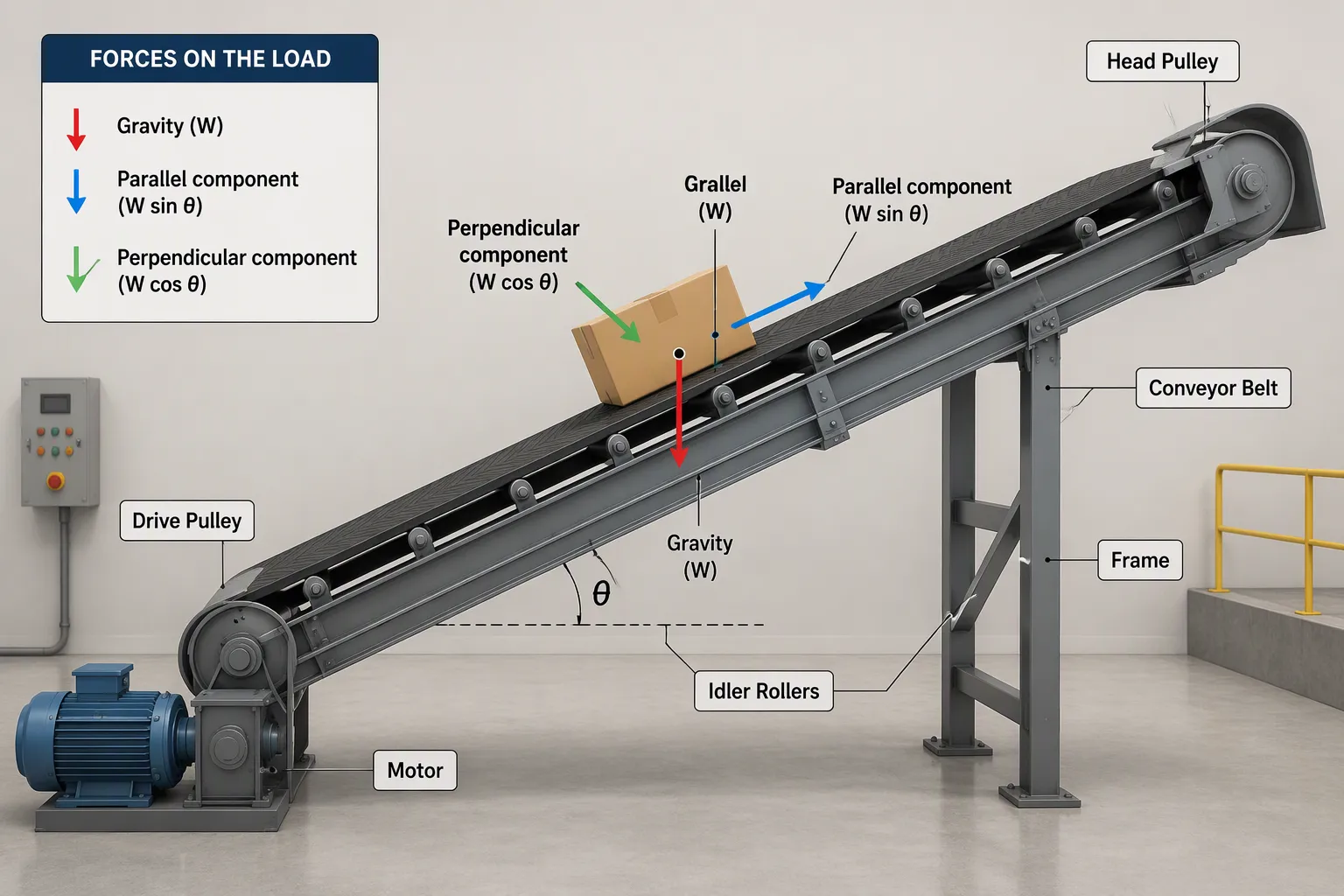
An inclined conveyor belt moves material upward against gravity. The motor provides the forward force; gravity pulls the loaded belt downward at the same time. These two forces oppose each other during normal operation, and the balance changes the moment the motor stops.
The gravitational force acting on a load on a slope has two components: one parallel to the belt surface, one perpendicular to it. In the formulas below, W is the weight of the moving load (belt plus material), θ is the incline angle, and μ is the friction coefficient between the material and the belt cover.
Parallel (downhill) gravity component: W sin θ. This is the force that drives rollback.
Perpendicular gravity component: W cos θ. This is the normal load that generates friction resistance.
Holding force to keep a load stationary on an incline, ignoring friction: F = W sin θ. This is the conservative value used for brake and holdback sizing.
Force to move a load up the incline at steady speed: F = W(sin θ + μ cos θ).
Force to control a descending load: F = W(sin θ − μ cos θ). A negative result means the load will not slide down on its own under those conditions.
Friction Between the Material and the Belt
The friction coefficient between the material and the belt cover determines how much resistance exists against the load sliding backward. Different materials, belt covers and surface textures produce different values. The table below shows indicative coefficients for rubber belt surfaces at various inclination angles.
Surface Type | Protrusion Angle (deg) | Inclination Angle (deg) | Coefficient of Friction |
|---|---|---|---|
Rubber | 15 | 23 | 0.38 |
Rubber | 15 | 28 | 0.40 |
Rubber | 15 | 32 (measured) | 0.52 |
Rubber | 0 | 18 | 0.38 |
Rubber | 0 | 23 | 0.32 |
Rubber | 0 | 28 | 0.40 |
Rubber | 0 | 32 (measured) | 0.48 |
Rubber (protrusion perpendicular, 90 deg) | 90 | N/A | 0.48 (mean static shear) |
Note: friction coefficients vary with material moisture, particle size, belt cover compound and surface wear. The figures above are indicative test data; confirm them against your belt supplier's data for the specific material being conveyed. "Protrusion angle" refers to the angle of the raised surface profile on the belt cover, measured from the belt plane.
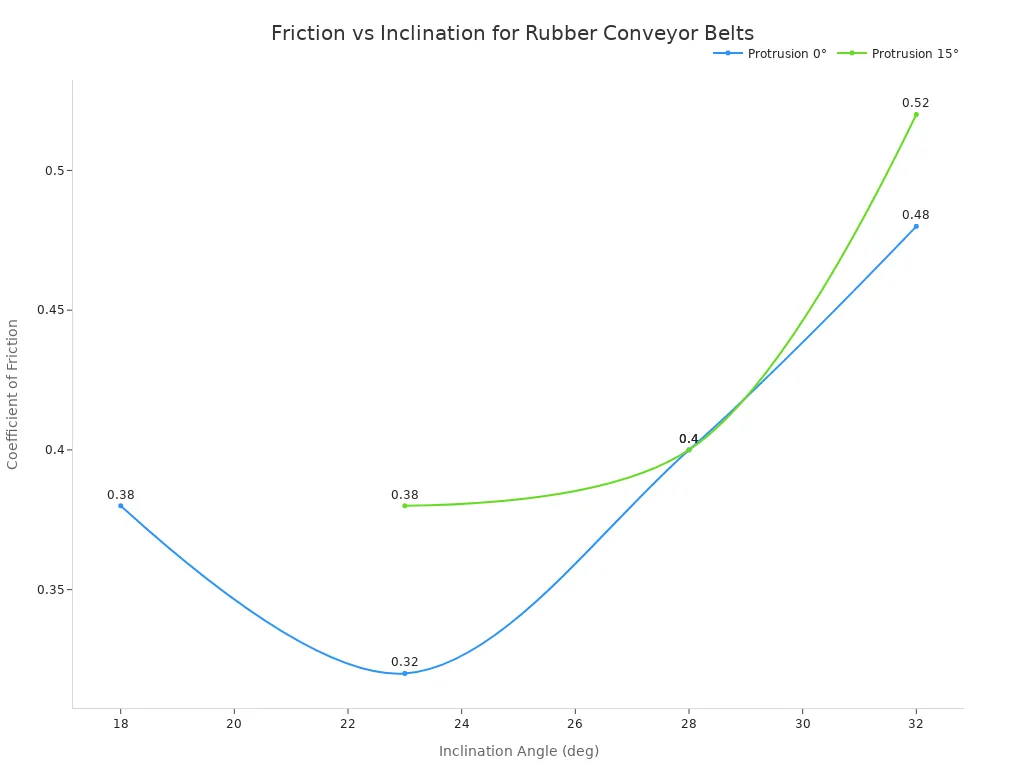
When the downhill gravity component exceeds the available friction, the material no longer travels with the belt: it slips backward on the belt surface. That is a material-retention problem, and it is solved with cleats, chevron profiles or a shallower angle.
What Happens at the Moment of Power Loss
The motor supplies the forward force that keeps the belt moving. When power fails, this forward force disappears instantly. Gravity takes over immediately, and the loaded belt begins to move backward. The reverse torque at the pulley changes the entire force balance.
The example below shows how that reverse torque is calculated for a typical inclined bulk conveyor.
Incline angle θ = 16°, so sin θ = 0.276.
Loaded mass moving on the incline W = 8,000 kg, giving a weight of about 78,480 N.
Head pulley radius R = 0.25 m (a 500 mm pulley).
Drive ratio i = 20:1.
Downhill force F = W sin θ = 78,480 × 0.276 ≈ 21,660 N.
Reverse torque at the pulley shaft T = F × R = 21,660 × 0.25 ≈ 5,415 Nm.
The same torque referred to the high-speed shaft = 5,415 ÷ 20 ≈ 271 Nm.
Required backstop rating at 2.0 shock factor ≈ 10,830 Nm at the pulley shaft, or about 542 Nm at the high-speed shaft.
Mounting position decides which figure applies. A backstop fitted to the gearbox high-speed shaft sees the divided value; one fitted to the pulley shaft sees the full value. Ignoring friction in this calculation is deliberate: it produces the conservative (larger) figure that brake and holdback sizing should use.
A loose belt makes this situation worse. Slack reduces the traction between the belt and the drive pulley, so the drive can no longer hold the load even while it is powered. Regular belt tension checks preserve that traction and reduce the hazard. A sudden stoppage from a mechanical or power failure is the most dangerous case of all: the belt carries full load weight, the motor provides no holding force, and only a mechanical device can prevent reverse movement.
The High Cost of Rollback
Safety Hazards for Personnel
A loaded inclined belt stores a large amount of gravitational energy. When a backstop is absent or has failed, gravity accelerates the belt downhill into a runaway condition. That creates a struck-by and crushing hazard for anyone working near the drive or along the incline. Loose material thrown from a reversing belt adds a second impact risk, and a belt that moves without warning is an entanglement risk for anyone touching it or its components.
These are not theoretical concerns. Conveyor and material-handling incidents remain a recurring cause of serious injury and fatality in mining and bulk terminals, and sudden equipment movement is one of the mechanisms recorded repeatedly in MSHA accident data. That is why a holdback is treated as a safety-critical component rather than an accessory.
Equipment Damage and Spillage
Uncontrolled reverse movement damages far more than the product being carried. The belt slams backward into the structure, and the idlers, pulleys and drive shaft absorb enormous reverse torque. A backstop acts directly to prevent this damage: it locks the shaft the instant forward power stops, shielding the conveyor structure and drive components from destructive forces.
The result of a rollback event is typically a combination of material spillage, damaged belting and drive components, an unsafe work area, and unplanned downtime. On a high-capacity bulk handling line, lost throughput during an unplanned stop can run into thousands of dollars per hour on top of the repair cost.
How Backstops for Inclined Conveyors Work
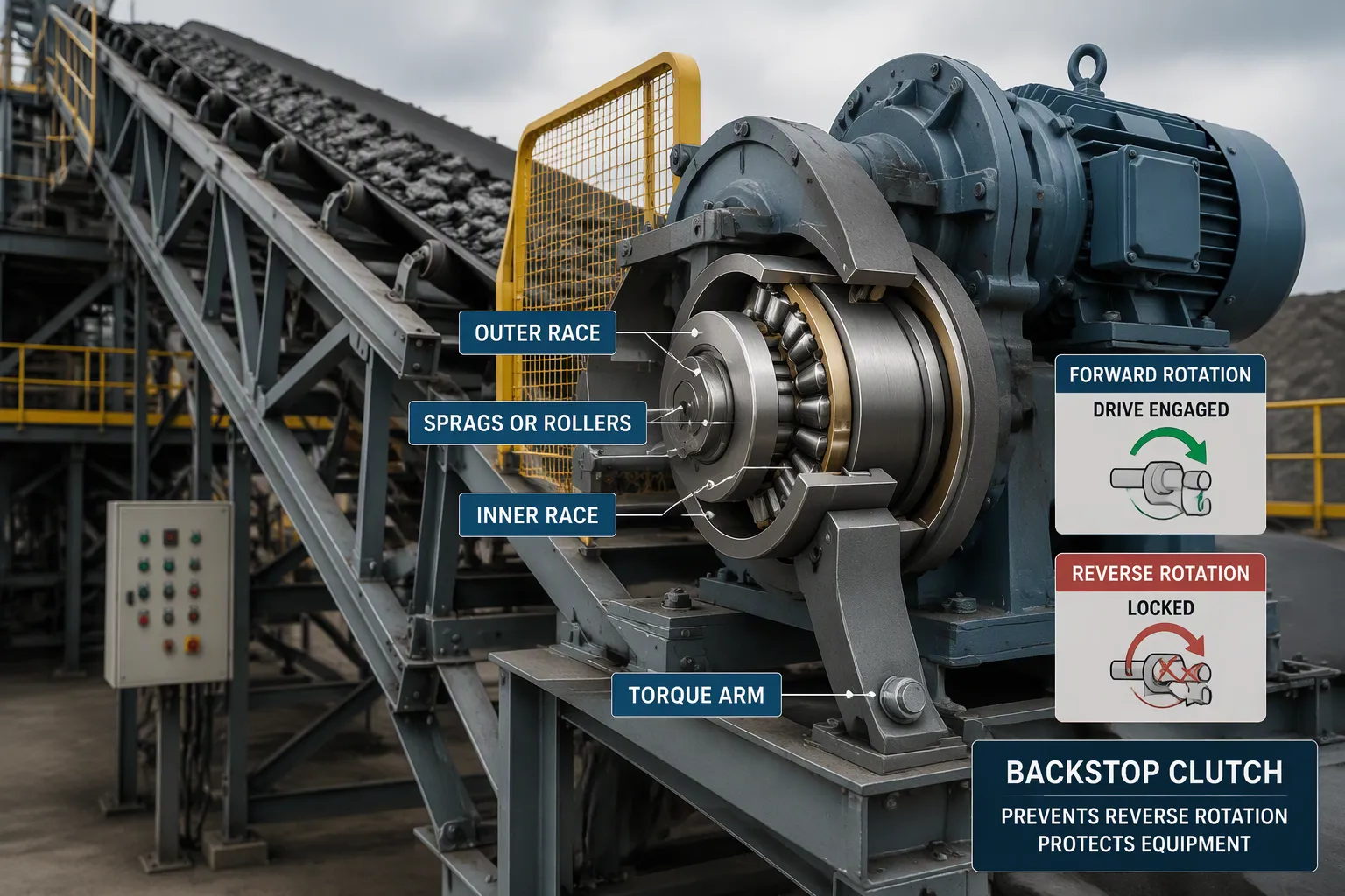
The One-Way Motion Principle
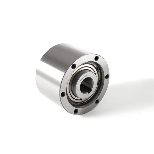
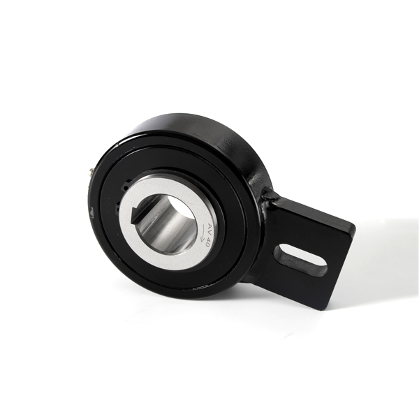
A backstop — also called a holdback, backstop clutch or one-way clutch, depending on the industry — is a mechanical component that prevents reverse rotation of a shaft. It acts like a one-way valve for rotary motion. The device allows the shaft to turn freely in the forward direction; the moment the shaft tries to rotate backward, the internal elements engage and lock it in place.
The mounting arrangement makes this possible. The backstop clutch is mounted directly onto the drive shaft, and the outer housing is held stationary by a torque arm attached to a rigid machine frame. During normal operation the shaft rotates freely and the clutch overruns without locking. If reverse rotation occurs, the internal elements engage immediately and block reverse motion, and the back-driving torque is transmitted through the torque arm into the machine frame.
This design protects the entire drive system. When power fails or the gearbox trips, the backstop prevents reverse rotation, avoiding belt damage, gearbox shaft breakage, motor damage and injury to personnel.
Common Types of Conveyor Backstops
Several backstop designs exist for different conveyor applications. Each uses a distinct engagement mechanism. The table below compares the two most common designs.
Holdback Type | Engagement Mechanism | Characteristics |
|---|---|---|
Sprag-type | Wedge-shaped sprags tilt into engagement when the inner race attempts reverse rotation | Compact, fast-acting, suited for high-frequency stops |
Roller-ramp (cam-roller) | Cylindrical rollers wedge up an inclined ramp inside the outer race | Handles higher torques, common on large overland conveyors |
Pawl-type | A spring-loaded pawl engages a ratchet wheel to block reverse rotation | Simple and robust, suited to lower-speed applications |
A sprag clutch is a one-way freewheel clutch. Instead of cylindrical rollers, it uses non-revolving asymmetric figure-eight shaped sprags. When the unit rotates in one direction, the sprags slip or free-wheel; when torque is applied in the opposite direction, the sprags tilt slightly, producing a wedging action that binds through friction.
The cam design works on a similar principle. The outer race is held stationary by a torque arm, and the cams contact the inner and outer races at two points, maintaining a constant strut angle with the centre line. When the inner race rotates in the forward direction it overruns smoothly, because the contact points do not act as a strut and the cams maintain only light spring-loaded contact. When the conveyor stops and the inner race rotates in reverse, the inner race is locked immediately: the contact points now act as a strut and prevent reverse rotation.
Both sprag and cam types are sized on the static rollback torque, calculated as the downhill load force multiplied by the pulley radius and divided by the drive ratio: T = W sin θ × R ÷ i. Engineers then apply a safety factor of 1.5 to 2.0 against shock loading, so the device can absorb the full load without failure.
Do Cleated Inclined Conveyors Need Backstops?
Cleats Hold Material, Not the Belt
Many operators assume a cleated belt can hold itself on an incline. The raised rubber profiles appear to lock material in place, and that assumption overlooks a critical distinction. Cleats prevent material from sliding backward on the belt surface; they do not prevent the belt itself from moving backward.
Chevron and cleated profiles are designed to retain material on the belt at steep angles and to release it cleanly at the head pulley. That is a material-retention function, not a reverse-motion safeguard. The profiles do not act on the belt, the pulleys or the drive, so they cannot stop the belt from reversing during an emergency.
Cleated conveyors use raised sections to carry bulk products at steep angles, and they do this effectively. Without a dependable backstop, however, even a cleated belt conveyor can run back. The combined weight of the belt and the material on a steep incline increases susceptibility to gravitational pull, and the result can be a catastrophic failure.
The incline angle determines how much cleat height is needed. The table below shows recommended profiles for various slopes.
Incline Angle Range | Recommended Cleat Height (Profile) |
|---|---|
18° – 25° | 5 mm – 10 mm (low profile) |
25° – 32° | 15 mm – 20 mm (medium profile) |
32° – 40° | 25 mm – 32 mm+ (high profile) |
As the incline increases beyond roughly 25° to 32°, progressively taller cleats become necessary to keep material in place. Cleat height addresses material retention only; it does nothing to stop the belt from reversing.
Why Cleats Are Not a Safety Device
Cleated belts serve material transport, not safety functions. The molded profiles act as physical barriers that trap bulk material in pocket-like compartments, dividing the load into segments and bearing the downward force of gravity so that material does not gain backward momentum on the belt surface.
The belt itself, however, remains vulnerable. A cleated belt can operate at greater incline angles than a smooth belt, but no universal incline limit exists: the achievable angle depends on product size, density, flow behaviour, cleat geometry and conveyor design. Steep inclines also create challenges at the loading and discharge points, so the complete conveyor system requires evaluation rather than selecting the belt by nominal incline angle alone.
Standard flat belts rely solely on surface friction. When the conveyor incline exceeds the material's angle of repose, typically 15° to 22°, material slides backward. Chevron belts solve that problem by molding raised rubber profiles, allowing stable conveying on slopes from 20° up to 40° without structural spillage. But as the incline approaches and exceeds the upper limit, even cleated belts become susceptible to material slip and to runback.
The risk of runback also increases when belt tension drops. A loose belt stretches under load, and that stretching reduces the grip between belt and pulley, so the entire belt can slip backward even while the cleats hold material in place. Properly selected and installed backstops remain essential on all inclined conveyor systems, regardless of belt type: they lock the shaft instantly when forward power stops, and no cleat design can replace that mechanical protection.
Not sure which backstop your conveyor needs?
Send us your incline angle, capacity, pulley diameter and drive ratio. Our engineers will calculate the rollback torque for your conveyor and recommend the right backstop clutch model — free of charge, usually within one working day.
Get a free sizing recommendation or browse the FXM backstop clutch range
Backstop vs. Brake vs. Cleats: Which Do You Need?
Backstops, brakes and cleated belts are frequently discussed as if they were interchangeable. They are not. Each addresses a different failure mode, and most inclined conveyors need more than one of them.
Device | What it does | Acts on power loss? | Typical role |
|---|---|---|---|
Backstop (holdback) | Blocks reverse rotation of the shaft | Yes — passive and fail-safe | Inclined conveyors, bucket elevators, pumps |
Spring-applied brake | Stops the drive and holds it after stopping | Yes, if spring-applied | Controlled stopping and parking duty |
Cleats / chevron belt | Holds material on the belt surface | No — does not act on the belt | Steep-angle conveying |
Anti-rollback idler | Adds friction against reverse belt travel | Partially | Light-duty, low-torque applications |
The practical rule is that a brake controls stopping, a backstop prevents reverse motion, and cleats keep material on the belt. A brake that holds the drive is a wearing component that needs adjustment and periodic replacement; a backstop has no wearing friction surface in normal operation and acts as the dedicated fail-safe layer. On most inclined bulk conveyors the two work together, and the cleats solve an entirely different problem.
Selecting Inclined Conveyor Backstops
Key Factors: Torque, Speed, and Mounting
Choosing the correct backstop for an inclined conveyor requires evaluation of three primary factors: torque capacity, operating speed and mounting configuration. Each one directly affects whether the device will protect the system during a power loss event.
Torque capacity is the most critical specification. The backstop must handle the static rollback torque generated by the loaded belt, calculated as T = W sin θ × R ÷ i, with a safety factor of 1.5 to 2.0 applied against shock loading. A device sized too small will fail precisely when it is needed most.
Conveyor speed also influences selection. Higher belt speeds generally reduce the torque required at the drive, but the backstop must still withstand the maximum speed and torque conditions the system may encounter. Selecting an unsuitable clutch can lead to damage during overrunning or sudden stops, and a high-speed conveyor demands a backstop designed for rapid engagement without excessive wear.
Mounting configuration matters equally. The backstop clutch mounts directly onto the drive shaft, with the outer housing held stationary by a torque arm attached to a rigid machine frame. This arrangement allows forward rotation freely while locking instantly on reverse motion. Proper alignment between shaft and housing prevents premature bearing wear and ensures reliable engagement.
When a Backstop May Not Be Required
If W(sin θ − μ cos θ) is negative for every operating condition — including a fully loaded, stopped belt — the load cannot run back on its own, and a holdback may not be strictly necessary. In practice, most inclined bulk conveyors are fitted with one anyway, because friction values change with moisture, wear and spillage, and because a single upset condition can turn a marginal slope into a runaway. Any decision to omit a holdback should be made by the conveyor designer on the basis of the calculation, not a rule of thumb.
Tianniu (Changzhou Tianniu Transmission Equipment Co., Ltd.) manufactures backstop clutches, electromagnetic clutches, torque limiters, locking assemblies and shaft couplings for bulk handling and power transmission applications. The standard FXM backstop series covers a range of torque capacities and bore sizes for conveyor drive shafts, and custom bores, torque arms and mounting arrangements are available. Send us your conveyor data — incline angle, capacity, pulley diameter and drive ratio — and our engineers will return a sizing recommendation. See the backstop clutch range.
Maintenance and Inspection
Regular maintenance is what makes an inclined conveyor backstop function correctly when it is needed. A backstop that fails during an emergency provides no protection at all, so scheduled inspections catch wear before it becomes a hazard.
The table below outlines recommended maintenance intervals for continuous operations.
Maintenance Interval | Recommended Backstop Procedure |
|---|---|
Weekly | Confirm that the anti-runback device is engaged and functional on inclined conveyors. |
Monthly | Inspect drive assemblies, including backstops, for wear, alignment and vibration. |
Quarterly | Verify that braking systems and backstops function properly under load. |
Quarterly to semi-annually | Confirm free forward rotation, verify locking in reverse, check torque arm security, inspect seals and confirm lubrication is current. |
These procedures apply to all inclined conveyor systems, regardless of belt type. A cleated belt does not eliminate the need for backstop maintenance: the mechanical device remains the reliable safeguard against reverse motion, and regular attention to it protects both personnel and equipment from the cost of rollback.
Gravity acts on the load the moment the motor stops. Whether the result is material slipping on the belt surface or the whole belt running back, the outcome is the same: a safety hazard and a repair bill. Cleats and belt friction address the first problem. Only a correctly sized holdback addresses the second.
Specify the backstop from the static rollback torque, fit it to the drive shaft, and inspect it on a schedule. That is what turns a design intention into a safeguard that works on the day it is needed. To have a backstop sized for your conveyor, send your incline angle, capacity, pulley diameter and drive ratio to the Tianniu engineering team.
FAQ
How quickly does a backstop engage during rollback?
Backstops engage almost instantly when reverse motion begins. The internal wedging elements lock the shaft within milliseconds of detecting backward rotation, so the belt never gains significant momentum. Fast engagement is what keeps stress on the rest of the conveyor system low.
Can a motor brake replace a backstop?
No, because the two do different jobs. A motor brake controls stopping during normal operation. A backstop is a passive device that holds the shaft whenever the drive is unpowered, and it has no wearing friction surface in normal running. A spring-applied brake also holds on power loss, but it is a wearing component that needs adjustment and periodic replacement. In practice the brake controls stopping and the backstop provides the fail-safe layer against reverse motion; both are needed on a safe inclined conveyor.
What happens if a backstop fails?
A failed backstop allows uncontrolled reverse motion. The loaded belt accelerates downhill, material spills from the belt surface, equipment suffers damage from reverse torque, and personnel face serious injury risk. Regular inspection prevents this scenario, and worn backstops should be replaced immediately.
Do all inclined conveyors require backstops?
Not every one, but the great majority of inclined bulk conveyors do. The deciding condition is whether the downhill component of the load can overcome friction and drive resistance: if W(sin θ − μ cos θ) is positive under the worst loaded condition, the belt can run back and a holdback is required. Because friction falls with moisture, wear and spillage, a slope that is safe on paper can still run back in service — which is why the calculation, not a fixed angle, should decide.
At what incline angle does a conveyor need a backstop?
There is no single universal angle. Runback depends on the load, the friction coefficient and the drive arrangement rather than on the slope alone, and a heavily loaded belt on a low-friction surface can run back at an incline of only a few degrees. Inclines of only a few degrees are therefore worth checking, and any conveyor where the calculation shows a positive downhill force under load needs a holdback.
How often should backstops be inspected?
Weekly verification confirms the anti-runback device is still engaged and functional. Monthly inspections check for wear, alignment and vibration. Quarterly checks verify proper locking function under load. These intervals suit continuous operations; harsher environments or high-usage applications may require more frequent checks.