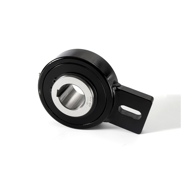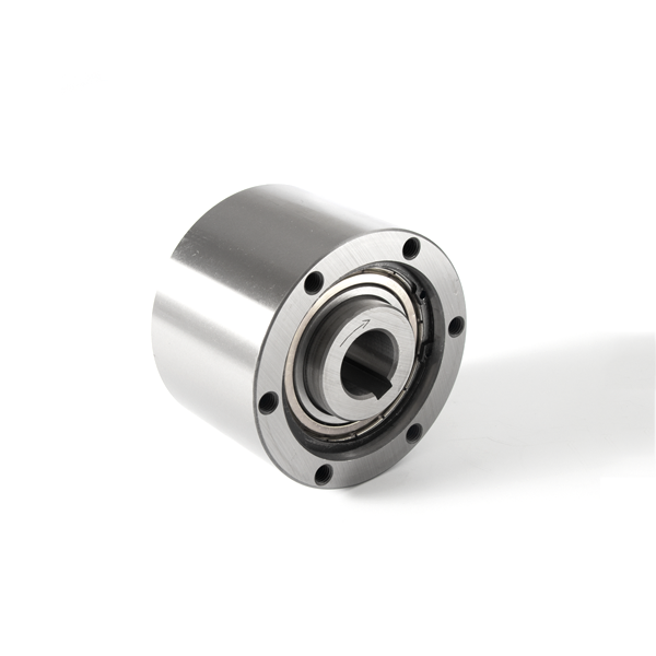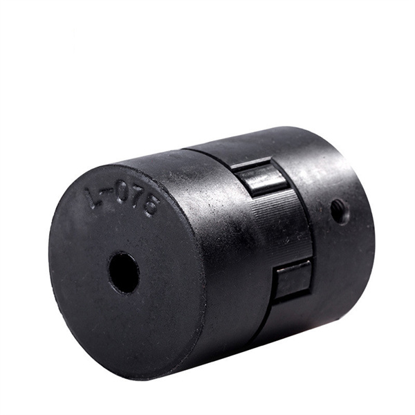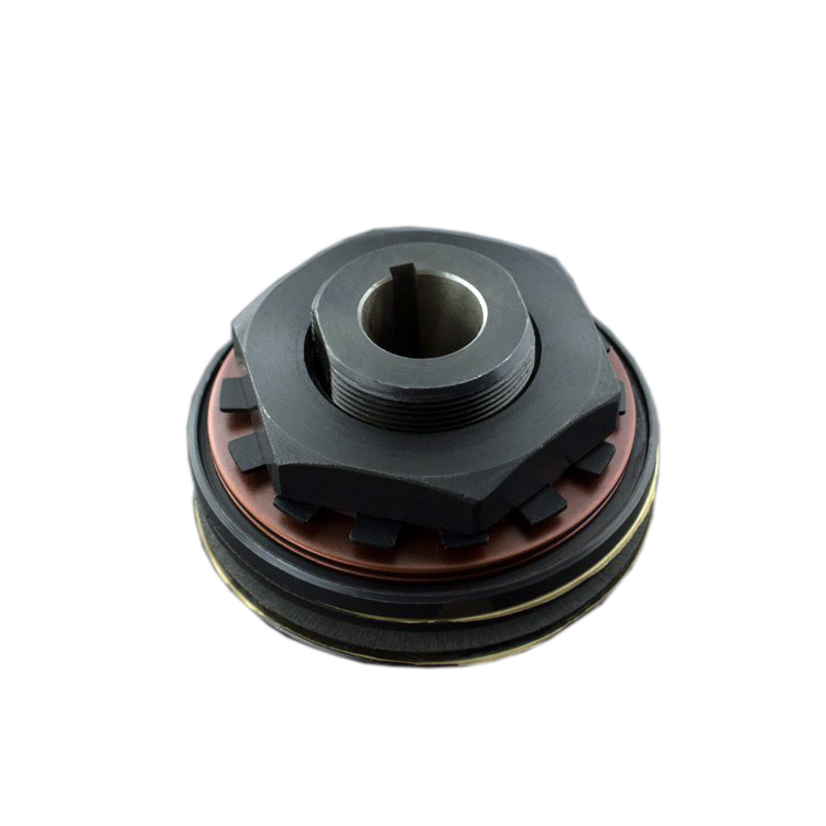




One Way Clutch: Types, Functions & Industrial Applications
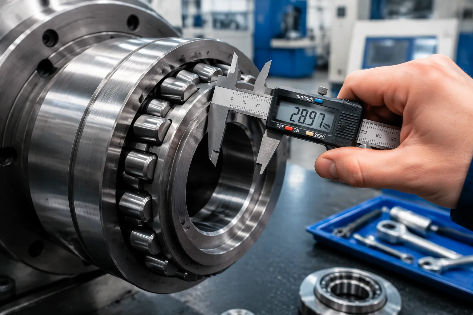
A one way clutch is a mechanical device that transmits torque in a single rotation direction and releases in the opposite direction. Engineers also call it an overrunning clutch or a one-way bearing. The unit locks when driven one way. It freewheels when the motion reverses. This behavior protects machinery from backward rotation, allows coasting, and enables precise intermittent movement. The article explains the working principle, the main types, the core functions, and the industrial applications of this component.
Key Takeaways
A one way clutch locks in one direction and freewheels in the other, protecting machines from backward rotation.
Roller and wedge clutches work best for high-speed overrunning and compact spaces.
Ratchet clutches provide firm, immediate locking for lower-speed indexing tasks.
One way clutches enable overrunning, backstopping, and indexing in many industries.
Choose a clutch based on load direction, speed, space, and cost for reliable performance.
How a One Way Clutch Works
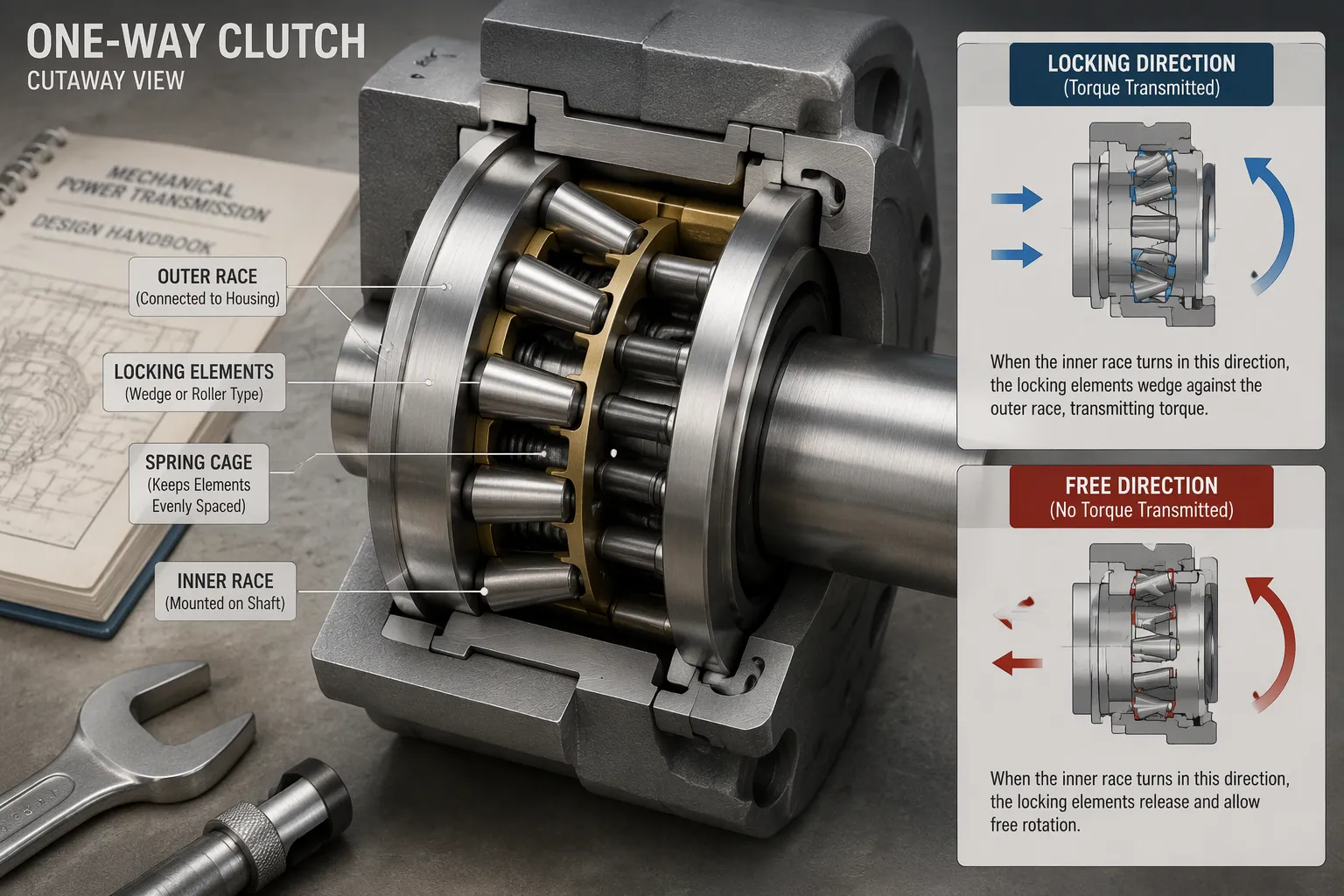
How a One Way Clutch Transmits Torque
The lock-and-freewheel mechanism is the heart of the design. Torque flows through the unit in one direction. The locking elements grip the races and the assembly becomes rigid. Motion in the opposite direction releases those elements. The races turn independently and the shaft spins freely.
The direction of relative rotation decides the state. The locking elements sit in tapered spaces between the inner and outer races. Rotation toward the narrow end of the space forces the elements into contact. Friction and wedging clamp the parts together. Rotation toward the wide end opens the gap. The elements lose contact and the clutch overruns.
The behavior varies slightly by element design. The following comparison draws on established engineering principles and industry standards.
Type | Locked Direction | Free Direction |
|---|---|---|
Wedge | Wedges deform and self-lock against the raceway | Wedges tilt and release the lock |
Roller | Rollers clamp in the narrow end of the wedge groove | Rollers move to the wide end and power is interrupted |
Cam | Cams engage during rotation in one direction | Cams disengage and the unit rotates freely |
Ratchet | Claws or pawls engage the teeth and block reverse rotation | Claws slide across the tooth surface with a clicking idle sound |
Key Components and Their Roles
Four elements carry the load. The inner race mounts on the shaft. The outer race connects to the housing or the driven part. The locking elements — needle pins, cams, wedges, or ratchets — bridge the gap between the two races. A spring or cage holds those elements in position and keeps them ready to engage.
Each part has a clear job. The races provide the hardened surfaces that the locking elements grip. The locking elements convert relative motion into either torque transmission or free rotation. The spring or cage maintains uniform spacing and prevents the elements from skewing. A cage also reduces wear by guiding the elements along the raceway.
Clutch Versus Clutch Bearing
The two terms describe related but distinct products. Industry experts explain that a one-way clutch is a mechanism that locks in one direction using needle pins or cams. A one-way clutch bearing combines that locking mechanism with bearing functionality. It transmits torque in one direction and supports the shaft at the same time.
This distinction matters during selection. A plain clutch needs separate shaft support from an adjacent bearing. A clutch bearing saves space and simplifies the assembly. Engineering guidelines note that integrated bearings reduce friction and let the clutch function reliably. The choice depends on the load path and the available room in the housing.
Types of One Way Clutch
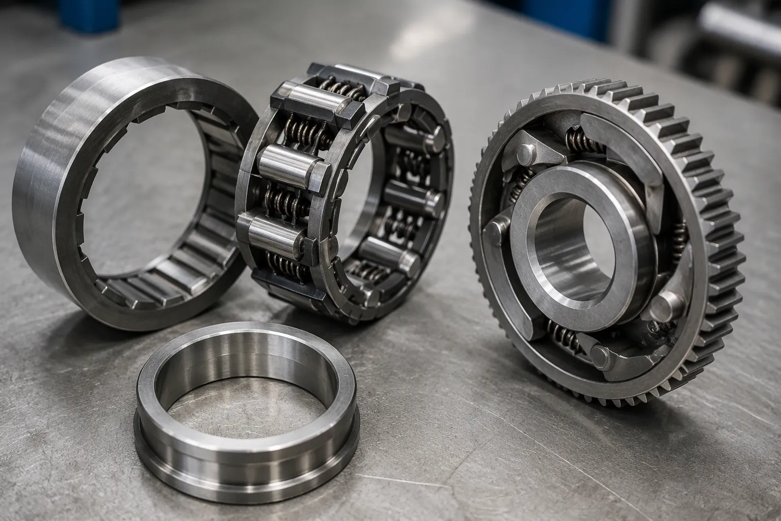
One way clutch designs differ mainly in the shape of their locking elements. Each shape trades off engagement speed, torque capacity, space, and noise in a different way. A compact comparison helps match the type to the task.
Roller and Wedge Clutches
Roller and wedge clutches use small cylindrical rollers or tilted sprags between the inner and outer rings. A holding spring keeps each element in position. Rotation in the locking direction pushes the elements into the narrow end of the gap. The elements wedge against both races and transmit torque. Rotation in the free direction moves them toward the wide end, and the shaft spins freely.
Tianniu's CKF series sprag clutches feature an outer ring, figure-8 wedges, a holding spring, and an inner ring. The wedges act like rollers and allow one-way motion with strong torque control. The company notes this design suits high-speed and heavy-duty work.
Sprag types use tiny spring-loaded pieces that tilt and lock the rings together. Our engineering team notes that sprag clutches offer fast engagement, high torque in a small space, and long life at high speeds. They may be chosen when zero-backlash and precise control are needed.
Patent analyses note a design trade-off in wedge angle. A smaller wedging angle improves wedging performance but reduces the effective friction layer for wear, shortening working life. A larger angle improves wear resistance but weakens torque capacity. The same sources note that rollers and wedges contact the races along a narrow line, which limits the friction force available under heavy load.
These types fit high-speed overrunning and compact spaces well. Their simple structure eases manufacture and maintenance, and they need no additional control device.
Ratchet Clutches
Ratchet clutches use pawls that engage teeth on a rotating part. Industry case studies describe pawls that engage immediately when torque is applied in the locking direction. This removes the tilting delay of sprag designs and gives instantaneous response. The teeth have inclined surfaces, so the pawls push onto them easily during switching while holding firm during torque transmission. Spring-loaded plate springs keep continuous contact between pawls and teeth, which absorbs vibration and reduces rattling and noise.
Ratchet types suit lower-speed indexing with positive engagement. The tooth-and-pawl contact gives a definite lock rather than a friction grip. This makes the type a good match for intermittent motion tasks where each step must register precisely.
Feature | Roller and Wedge | Ratchet |
|---|---|---|
Locking element | Rollers or sprags | Pawls and teeth |
Engagement | Wedging friction | Positive tooth contact |
Best fit | High-speed overrunning, compact spaces | Lower-speed indexing |
Both families serve distinct roles. Roller and wedge units favor smooth, quiet running at speed. Ratchet units favor firm, immediate locking at lower speed.
Core Functions
Overrunning and Backstopping
Overrunning means the output turns faster than the input. The driven part coasts or freewheels ahead of the drive, and the clutch releases so no torque flows back through the shaft. This function supports coasting loads and standby drive arrangements.
Backstopping is the opposite duty. The clutch allows free rotation in the forward direction and locks the moment torque reverses. Mechanical engineering resources describe a loaded inclined conveyor that would run back when the drive stops. The outer race is fixed to the machine frame, usually through a torque arm, and the inner race spins forward with the drive. Any backward motion locks the unit and holds the load. Technical documentation also notes a pump arrangement with an electric motor on one end of the shaft and a standby diesel engine on the other, isolated by a clutch.
Backstopclutch.com lists the practical points of this duty:
A backstop clutch stops a loaded conveyor on a slope from rolling back when the drive stops.
The outer race stays still on the machine frame, while the inner race spins forward.
Backward movement makes the clutch lock and stop the load.
Incline conveyors, bucket elevators, and pump systems use these units for safety.
Industry standards add that the clutch engages with a fixed frame as soon as torque reverses. This protects critical equipment and supports worker safety.
Indexing and Positioning
Indexing converts continuous rotation into intermittent motion. The input turns steadily, and the clutch grips for part of each cycle and releases for the rest. The output advances in steps instead of running continuously.
Packaging and assembly machinery rely on this behavior. Manufacturing experts note that one-way bearing clutches appear in conveyors, index tables, and packaging machines. The clutch drives the indexing table, and packaging machines use it to control the packaging material for precise operation. Industry reports indicate that industrial indexing can demand millions of micro-start and micro-stop cycles each day. A synchronized dual-cage freewheel snaps all locking elements into position at once, which removes angular backlash and holds feeding accuracy at high cycling speeds. A one way clutch built to this standard keeps each step registered and limits scrap.
Industrial Applications
Automotive, Aerospace, and Equipment
Automatic transmissions rely on sprag clutches inside planetary gear sets and torque converters. Transmission specialists report that these units support gear shifting and torque multiplication. The same sources note a growing role in hybrid and electric vehicles, where the clutch helps manage power distribution between the internal combustion engine and the electric motors. Continuously variable transmissions also use them for smooth power delivery.
Aerospace systems use one way clutch elements in actuators that control flight surfaces. Reliability and efficiency matter here, because safe and precise aircraft operation depends on them. Industrial equipment forms the third major group. Conveyors and pumps use backstopping duty to hold loads on inclines and to isolate standby drives.
Domain | Application Area | Function |
|---|---|---|
Automatic transmissions | Planetary gear systems and torque converters | Gear shifting and torque multiplication |
Automatic transmissions | Hybrid and electric vehicles | Power distribution between engine and motors |
Automatic transmissions | Continuously variable transmissions | Seamless power delivery |
Aerospace | Flight surface actuators | Safe, precise control |
Tianniu's backstop clutches are designed for reliable one-way rotation and reverse-motion prevention across industrial applications. The company also offers shaft couplings, locking assemblies, electromagnetic clutches, and torque limiters for complete drivetrain support.
Consumer Products and New Energy
Small spring wrap clutches serve tape recorders, small appliances, and printers. Industry monitoring platforms list a torque range of 0.1 to 10 Nm and a speed range of 3,000 to 10,000 for this type. Power tools use a one way clutch to drive the reciprocating action of the drill bit. Washing machine dehydrating buckets lock during the spin cycle and release during draining. Bicycle flywheels and hand tools commonly use the ratchet type.
New energy equipment presents growing demand. Renewable energy applications describe wind turbine yaw systems that use the clutch to guard against mechanical overload when wind direction shifts suddenly. Wave power generation uses it to convert reciprocating wave motion into unidirectional rotation. Hybrid systems use it to coordinate the power switch between motor and engine.
Selection Criteria
Matching Type to Application
Load direction comes first. A one way clutch locks in a single direction, so the machine rotation and the mounting orientation must match the chosen unit. The duty mode then narrows the field. Overrunning duty makes freewheel speed the limiting factor. Indexing duty puts torque and step accuracy at the center. Backstopping duty demands holding torque and lock-up reliability, while freewheel speed usually stays low.
Space and shaft fit follow. Technical specifications require that race hardness reaches HRC 60–62, with a plain race width free of recess. Industry monitoring platforms list a typical misalignment tolerance of 0.1° to 0.5°, so the housing must hold the races square. Duty cycle and operating temperature complete the picture. Standard industrial units cover operating temperatures from -30°C to +120°C, with overrunning speeds ranging from hundreds to several thousands of RPM, depending on the clutch size and design.
Performance and Cost Factors
Torque capacity sets the size of the unit. Engineering best practices advise keeping peak torque below 80% of the clutch rating and applying a service factor of 1.5 to 2.0 times the calculated peak torque. Manufacturers typically add that peak torque is about twice the rated TKN value. A clutch with too little margin wears faster under shock loads.
The three main families trade performance against price. Market analyses report that sprag clutches reach up to 50,000 Nm and 3,000–8,000 rpm, roller bearings reach up to 8,000 Nm and 5,000–15,000 rpm, and cam clutches reach up to 20,000 Nm and 1,500–5,000 rpm. Market data also indicates varying price ranges depending on the complexity and torque density. Roller units are generally the most cost-effective for high-volume builds, cam units sit in the mid-range, and sprag units command a premium due to their high precision and compact size. The chart below compares maximum speed and relative cost across the three types.
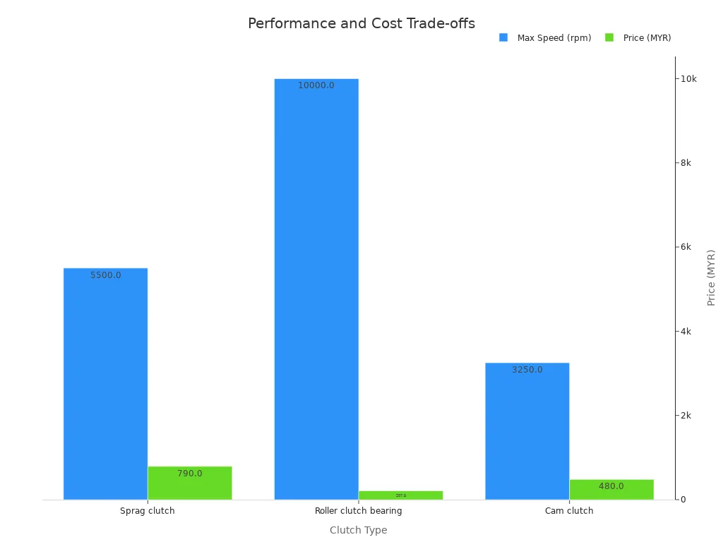
Roller types suit high-volume, cost-sensitive builds. Sprag types justify their higher price where space is tight or speed is high. Cam types fit indexing and conveyor backstop duty. Whatever the choice, a one way clutch brings compact design, reliable one-way transmission, and low maintenance to the drivetrain.
Conclusion
A one way clutch is a mechanism that locks in one rotation direction and freewheels in the other, and engineers also know it as an overrunning clutch or a one-way bearing. Roller and wedge designs serve high-speed overrunning and compact spaces best. Ratchet designs serve lower-speed indexing with firm, positive engagement. Selection should follow application fit, load direction, speed, and cost rather than loyalty to one type. Demand for these components continues to grow across industrial machinery and new energy equipment, where reliable one-way rotation supports safer, more efficient operation.
FAQ
How do I confirm the locking direction before mounting?
Rotate the inner race by hand in both directions. One direction turns freely. The other direction locks the races together. Mark that locked direction on the housing. The machine rotation must match it. A reversed installation gives no backstop protection at all.
Does a one-way clutch bearing need separate shaft support?
No. A clutch bearing carries shaft load and transmits torque in one direction. A plain one-way clutch does not support the shaft. It needs an adjacent bearing to hold radial load. Check the load path before choosing between the two products.
What causes a one-way clutch to slip under load?
Slip usually points to worn locking elements or a damaged raceway. Race hardness matters here. Technical specifications require that race hardness reaches HRC 60–62, with a plain race width free of recess. Soft or recessed races let the elements lose grip. Replace worn parts and restore the specified hardness.
How much torque margin should I allow?
Engineering best practices advise keeping peak torque below 80% of the clutch rating. Apply a service factor of 1.5 to 2.0 times the calculated peak torque. Shock loads and frequent cycling raise the required margin. A unit sized too close to peak torque wears faster.
Where does a backstop clutch fit best?
Backstop duty suits loaded inclines and standby drives. Incline conveyors, bucket elevators, and pump systems use these units for safety. The outer race fixes to the frame through a torque arm. The inner race spins forward with the drive. Reverse motion locks the unit and holds the load.
Partner with Tianniu for Your Drivetrain Solutions
Selecting the right one-way clutch is critical for the safety and efficiency of your machinery. At Tianniu (Backstop Clutch), we engineer high-precision sprag, roller, and backstop clutches tailored to your exact torque and speed requirements.