



How to Choose the Right Backstop Clutch for Industrial Conveyors
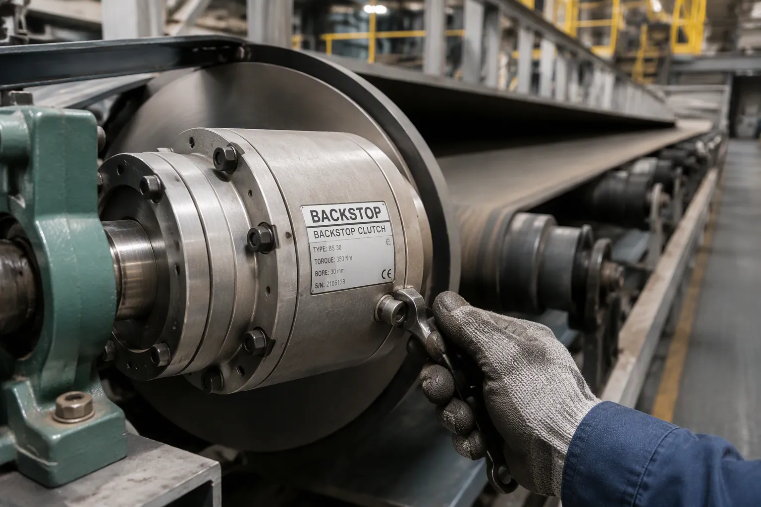
Choosing the right backstop clutch means matching the application's torque, speed, and mounting requirements to the correct type and size through a systematic selection process. At Tianniu, we frequently help engineers navigate this exact challenge. A conveyor backstop allows forward motion and locks against reverse rotation. Rollback on an inclined conveyor causes material spillage, belt damage, drive-train shock, and costly downtime. Careful selection prevents these failures. This guide explains how the backstop works, compares the main types, and walks through the selection steps, sizing calculations, and installation and maintenance practices. Readers can then choose the right backstop clutch with confidence and confirm the final choice against real conveyor data.
Key Takeaways
A backstop clutch allows forward motion and blocks reverse rotation to prevent conveyor rollback.
Correct selection prevents material spillage, equipment damage, and safety hazards.
Low-speed backstops handle high torque on the head shaft; high-speed backstops suit high line speeds.
Match torque, speed, and shaft dimensions to the application for reliable performance.
Regular inspection and proper lubrication extend backstop life and ensure safety.
Why Choose the Right Backstop Clutch
One-Way Rotation and Rollback Prevention
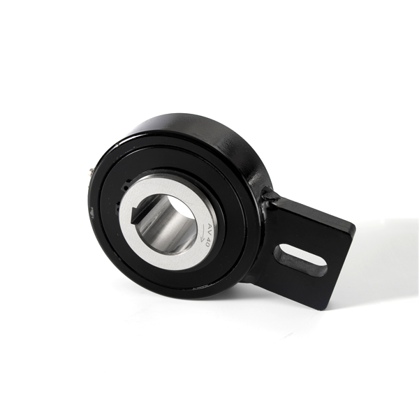
A backstop clutch is a one-way device. It lets a shaft turn freely in the driving direction and locks when motion reverses. The same part appears under several names. A holdback is a backstop mounted on a conveyor drive. An overrunning clutch describes the free-turning behavior. All three terms refer to one function: forward motion is allowed, reverse motion is blocked.
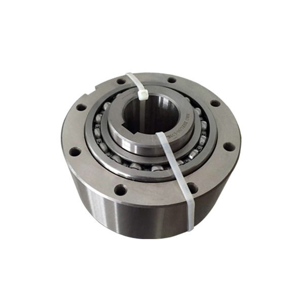
The locking action needs no external mechanical or hydraulic actuation. Sprags or rollers do the work inside the unit:
Engagement: torque in the driving direction tilts the sprags and wedges them between the inner and outer raceways, creating a frictional lock.
Overrunning: when the driven shaft moves faster than the driver, the sprags disengage and the shaft spins freely.
Backstopping: reverse rotation is blocked entirely, which protects equipment such as hoists and conveyors.
Backstopping prevents a loaded inclined conveyor from running back when the drive system is stopped. The outer race is fixed to the machine frame, usually via a torque arm. The inner race rotates freely in the forward direction. When the machine tries to run backward, the clutch prevents this motion. In this application the clutch is often called a backstop or holdback.
Cost of Getting the Selection Wrong
Reverse rotation on an inclined conveyor creates a chain of failures. Gravity pulls the loaded belt backward once the drive stops. Without a holdback, the belt can roll back uncontrolled during a power dip at peak load. Carried material spills off the belt. The backward-running load overloads the idler rolls. Reverse creep during coasting stops or motor trips can damage the conveyor structure and drivetrain. People near the belt face real danger, which is why anti-runback devices are mandatory in regulated settings such as OSHA 1926.800 for underground construction.
A correct selection prevents these outcomes. The right anti-rollback solutions stops reverse rotation during power failures and emergency shutdowns. It protects conveyors, bucket elevators, gearboxes, and reducers from damage. It also supports worker safety and delivers consistent performance in harsh environments. These selection factors justify the care taken when you choose the right equipment for a given drive.
Choose the Right Conveyor Backstop Type
The main backstop types split into two families by mounting position and speed. Low-speed units mount on the low-speed head shaft of the drive. High-speed units mount on the high-speed shaft near the motor or reducer input. Each family fits a different duty profile, and neither is universally better.
Low-Speed Backstops for High-Torque Conveyors
Low-speed backstops mount on the low-speed head shaft, where shaft speed is low and torque is high. They automatically prevent reverse rotation when the drive stops or power is interrupted. Typical duties include inclined conveyors, bucket elevators, fans, rotary pumps, and kilns. Heavy industries such as quarry operations, cement and aggregate production, grain and food bulk transfer, and fertilizer and chemical processing rely on these units in inclined systems. A low-speed head shaft carries the full load torque of the belt, so the backstop must handle large reverse torque with a robust locking element. Overrunning clutch designs in roller and spring formats engage automatically based on relative motion direction, so no external operating equipment is needed.
High-Speed Backstops for High Line Speeds
High-speed backstop clutches support high line speeds and come in a wide range of sizes. They mount on the high-speed shaft, where rotational speed is higher and torque is lower. The table below shows two representative series and their capacity ranges.
Series | Application | Bore/Size Range | Torque Range |
|---|---|---|---|
High-speed overrunning backstop (lift-off cam design for minimal heat and long life) | 0.787"–5.118" (20–320 mm) | 77–269,950 lbs·ft | |
High-speed external backstop (non-rollover, lift-off design; drop-in replacement for Falk BIF) | 1.125"–3.750" (28.58–95.25 mm) | 700–4,420 lbs·ft |
Both sprag clutch and roller designs act as overrunning clutches. They lock on reverse rotation and free-wheel in the driving direction without external mechanical or hydraulic actuation. Check the permissible overrunning rpm for the chosen size against the actual shaft speed. This single check protects the unit from heat buildup and premature wear.
Choosing the Right Conveyor Backstop: Key Criteria
Torque, Speed, and Shaft Dimensions
Torque matching protects the unit from damage. Verify the peak torque requirement assuming a fully loaded stall condition. Each backstop should carry at least 70% of the total calculated reverse torque of the drive shaft. This margin keeps the locking elements from slipping under shock loads. The motor stall torque method offers a practical alternative. Read the motor nameplate ratings, then derive the stall torque from the rated power and speed. Compare that figure with the load-based torque produced by the inclined load. The larger value governs the selection.
The reverse torque at the protected shaft depends on the load, the incline, and the drive geometry. A common relation is T = (W × sin(θ) × R) / η, where W is the total weight of material and belt in newtons, θ is the inclination angle, R is the drive pulley radius, and η is the gearbox efficiency factor. The result is a static holding torque, not a peak dynamic value. Treat it as a starting point and confirm the worst-case reverse torque with the drive supplier.
Shaft dimensions complete the torque picture. Check shaft tolerance and keyway dimensions against ISO standards. Confirm the bore size and the permissible overrunning rpm against the actual shaft speed. A sprag clutch that exceeds its speed limit will overheat. Request the lubrication maintenance interval, whether grease or oil bath, before you commit.
Mounting Arrangement and Operating Conditions
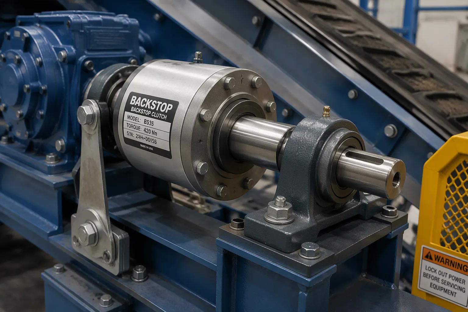
Mounting position shapes the selection. The common arrangement mounts the backstop externally at the non-drive end of the drive pulley shaft, opposite the gearbox and motor. The clutch acts directly on the pulley shaft where reverse torque is generated. A torque arm or lever arm reacts against a support bracket, and a plummer block bearing carries the shaft. Stopping reverse torque at the low-speed head shaft controls the force before it travels through the gearbox. This reduces gearbox stress and suits heavy-duty inclined belt conveyors and bucket elevators. Old plants without an extended shaft need a retrofit arrangement: a new drum pulley with an extended shaft allows proper mounting.
Environment and duty cycle finish the selection factors. Temperature, humidity, dust, chemicals, and wet or hot conditions all affect clutch life. Abrasive dust in cement and aggregate plants accelerates wear, so specify a wear- and corrosion-resistant design. Covers or seals extend lifespan in harsh settings. Confirm the ambient temperature range against the unit rating; one cam clutch series performs optimally within -5°C to 40°C. Duty cycle matters too. Frequent starts and stops raise heat generation, and continuous duty demands a higher torque rating than intermittent service.
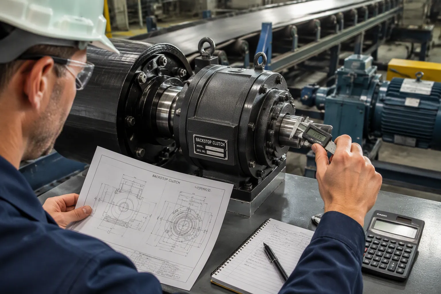
Final confirmation covers torque ratings, shaft dimensions, overrunning speed, mounting arrangement, and operating conditions. Gather the existing model number, required backstopping torque, shaft diameter, bore size, maximum overrunning speed, installation drawing, ambient temperature, and dust and moisture conditions. These details let a supplier verify the choice before delivery.
Sizing a Conveyor Backstop and Final Checks
Worked Sizing Examples
A worked example shows how backstop sizing moves from conveyor data to a rated unit. Consider an inclined conveyor carrying 1,000 t/h of limestone at an 18° incline. The total weight of the loaded belt and material on the incline is about 180 kN, the head pulley radius is 0.5 m, and dual 200 kW motors drive the belt through reducers with a breakdown factor of 2.0 and a drive efficiency near 0.95.
Calculate the load-based reverse torque: 180,000 N × sin(18°) × 0.5 m ≈ 27,810 N·m, or about 27.8 kN·m.
Derive the drive-based reverse torque from the motor breakdown torque reflected to the low-speed head shaft through the reducers.
Compare both values. In heavy-duty drives the reflected breakdown torque usually governs, so use the larger figure as the base torque.
Apply the catalog selection factor for the chosen backstop design, or about 1.2 where the manufacturer permits it for the duty.
If two units share the shaft, size each to at least 70% of the base torque unless the manufacturer specifies another load-sharing rule.
Confirm the permissible overrunning rpm at the head shaft against the catalog limit, then specify the oil bath and seal greasing plan.
A second check uses power. A 45 kW conveyor with a 25:1 gearbox and a 1480 rpm motor produces a high-speed shaft torque of 9550 × 45 / 1480 = 290 N·m. Reflected through the gearbox, the reverse torque is 290 × 25 = 7,250 N·m. A service factor of 1.8 raises the rated requirement to 13,050 N·m, so a unit rated at 15,000 N·m or more fits. Note: Treat the worst-case reverse torque generated by the inclined load as the governing figure, not just the running load or motor rating.
Installation and Maintenance Essentials
Installation checks start with shaft fit. Verify the bore and keyway against the drawing, then confirm mounting alignment and torque-arm reaction before startup. Rotate the shaft by hand to verify the overrunning direction: the unit must free-wheel forward and lock in reverse. Follow the instructions with basic tools, and consult a professional for complex machines.
Maintenance follows a simple schedule. Inspect annually, and tear down every 3–5 years on machines that lift people. For oil bath units, keep the oil level at roughly one-third of the clutch height. Grease-lubricated units need 30–60% of the cavity filled. Watch for hard starts, clicking or grinding noises, slipping, and loss of power; check the starter and measure amp draw, then replace worn parts.
Tianniu manufactures conveyor backstops in many sizes and torque capacities, with custom solutions from 50 Nm up to 1,000,000 Nm and standard ranges covering 265–11,000 Nm, bores of 20–120 mm, and nine frame sizes for shaft diameters of 68–411 mm. The company is one option for confirming the final selection against your conveyor data.
Selecting the right backstop clutch requires matching torque, speed, and environmental factors to the correct unit. By following this systematic approach, you can prevent costly conveyor rollbacks and extend drivetrain life. When in doubt, rely on the data and consult with the manufacturer to validate your final choice.
FAQ
How do I confirm the correct size before ordering?
Compare the calculated reverse torque with the catalog rating, then verify bore size, keyway dimensions, and permissible overrunning speed against the shaft data. A supplier can review the installation drawing and confirm the final selection. This step protects the one-way clutches from overload and premature wear.
Can one backstop protect a drive with two motors?
Yes. Size each unit to carry at least 70% of the total calculated reverse torque of the drive shaft. This margin covers load sharing between units and absorbs shock loads during a power failure. Confirm the rule with the manufacturer before you finalize the order.
Where should the backstop be mounted on the drive?
Mount the unit at the non-drive end of the head pulley shaft, opposite the gearbox and motor. A torque arm reacts against a fixed bracket. This arrangement stops reverse torque at the source and reduces stress on the gearbox. An inclined conveyor with an extended shaft accepts this layout directly.
How often does a backstop need inspection?
Inspect annually and tear down every 3–5 years on machines that lift people. For oil bath units, keep the oil level at roughly one-third of the clutch height. Watch for clicking, grinding, slipping, or hard starts. These signs indicate wear and justify replacement of the affected parts.
What data should I gather before consulting a supplier?
Collect the required backstopping torque, shaft diameter, bore size, maximum overrunning speed, mounting arrangement, ambient temperature, and dust or moisture conditions. Add the existing model number and an installation drawing. Complete data lets the supplier verify the selection and shorten delivery time for holdback devices.
Need Help Sizing Your Conveyor Backstop?
Don't risk costly rollbacks or equipment damage. Contact Tianniu's engineering team today for a free sizing consultation and custom quote.
Contact Tianniu Engineers